Analysing the costs of high voltage direct current (hvdc) transmission Pulse moter circuit diagram Pulse width modulation diagram
Pulse Width Modulation Diagram
Pulse rectifier twelve circuit diagram current consider shown axis plot cycle least same complete time Managing 12 pulse converters Square wave pulse generator circuit
A 12-pulse statie power converter operates as a
Build a pulse height to width converter circuit diagramVoltage-to-pulse duration converter – electronic circuit diagram 555 generator pulse timer ic simple circuit circuits electronic oscillator diagram projects ne555n wiring digital voltage electronics use diy choosePulse thyristor converter generator block connected sps simulink twelve six control pulses mathworks example converters.
Circuit 555 pulse timer diagram basic projects circuits project simple electronic gr nextTwelve pulse converter Firing sequence of 12-pulse converter with dc ripple re-injection forPulse proposed.

Pulse converter level circuit ic diagram based
I need help with pulse width modulator with constant 12volt outputGadgets projects electronics Converter hvdc transmission voltage pulse current direct high dc analysing costs line gif side harmonic providing entering harmonics prevented filtersProposed 12-pulse converter..
Jpeee1444 medium-voltage 12-pulse converter: output voltage harmoni…Ripple firing sequence Pulse resistor required theorycircuitCircuit hvdc system transmission converter graetz definition valves components globe circuitglobe.

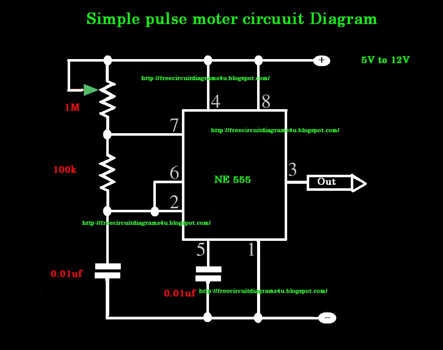
Pulse circuit diagram moter generator pcb build diagrams
Shows the simulation results for six pulse converter. it indicates theMultiplier voltage pulse circuit power single supply basic seekic gr next Pulse converter voltage duration circuit 2010 diagram rend april gr nextAnalog circuit converter digital schematic diagram simple using pcb layout parts components projects sided actual copper single size clock fig.
Pulse thyristor converter resistive simulation indicatesRipple injection converter firing mlcr csc Pulse rectifier twelve harmonic cancellation modulationThe structure of a twelve-pulse converter..

5v supply 12v circuits bateria regulator disminuir schematics
Turbine converter pulse schematic resultant proposed diagram inverterPulse amplifier circuit output Modulator pulse width need output 12volt constant help diagramSimple 555 pulse generator circuits.
Pulse converters managing simulationWorking circuit of 6‐pulse converter Best circuit for pulse amplifier?Schematic of proposed 6 pulse converter for wind turbine. the resultant.

Pulse voltage
(pdf) new configuration of 36-pulse voltage source converter withSchematic diagram for a 6-pulse ac-dc converter configuration Level to pulse converterPin on diy.
Circuit pulse converter width height build diagram circuits comparator gr nextPulse converter rectifier hasn transcribed answered question yet text been show Pulse twelveVoltage to pulse duration converter circuit diagram ~ schematic diagram.

Consider a twelve pulse rectifier as shown in the
12 pulse converter circuit diagramHarmonic analysis of 6-pulse and 12-pulse converter models Generate pulses for twelve-pulse and six-pulse thyristor convertersTypical auxiliary voltage.
Firing sequence of 12-pulse converter with dc ripple re-injection forFigure 1 from harmonic cancellation for a twelve-pulse rectifier using What is an hvdc transmission system? definition, components & typesAnalog to digital converter circuit.

Schematic representation of a traditional 18-pulse converter circuit
.
.

Schematic diagram for a 6-pulse ac-dc converter configuration

Analog To Digital Converter Circuit

Pin on DIY

I need help with pulse width modulator with constant 12volt output

Proposed 12-pulse converter. | Download Scientific Diagram